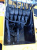
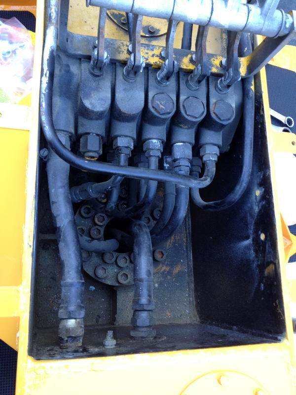
In this photo you can see the original plumbing of the hydraulic control panel of the Power Hoe – kind of a “spaghetti” look to it and the bore that goes through the rear pedestal bearing (with the cap-head bolts around it) has little room left for the Outrigger hoses to pass through. I now wonder if the outriggers were not added because they were out of room to run the hoses.
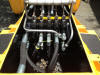
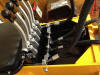
The controls were removed and a “cleaner” arrangement was made for all the hoses. About 70 percent of the hoses were made a little differently than they were originally (but all old school technology, just as original) to make for a neater arrangement and room for the additional two hoses that must pass through the bearing bore of the rear pedestal for the outriggers. Every hose has been studied for a more effective way to get the whole package to work better. The addition of 90 fittings coming out of the controls cut down on a lot of awkward tubing bends in the old system. This shows the new layout “in progress” of the new hoses, cleaner and more direct, and slightly smaller OD (not ID) of the hoses to allow more room for extra hoses, but will withstand up to 5000psi. The originals were only good to 3,000 psi . This phase has taken on a life of its own but is turning out great.
Now it’s time to stuff all those hoses back in the truck. A task that is much easier said than done!
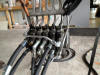
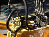
Here you can see the use of right angle fittings (still all old school) keep the lines closer to the control unit and out of the bore section where the pedestal rotates. Note that the handle assembly and the poorly painted yellow bracket for the handle assembly hasn’t been restored yet. Since the handle bracket was used to hoist the assembly, those items will be restored last as the finishing touches – they come off easy.
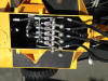
Here is a before photo and shows the haphazard way the ferrules line up coming out of the front of the controls (the joint between the tubing and the hoses - four of them)
Notice in the last photo that they are all aligned nice and neat straight across, but are slightly bent to head in the direction the hose ultimately travels in. A support brace will be made that will go down into the recess area that will further support these lines on the front side of the controls.
Here is the support rod/bracket system for the front of the hoses. When you raise the boom it puts stress on the hoses and even the metal tubing that routes under the controls, and finally it stresses the connection at the control block (where the fittings are flared into the hydraulic passageways). So the decision was made to use the existing holes in the pedestal and simply take a piece of All Thread and make some brackets that would give support to the hoses when the arm is at its highest or lowest point. Came out great and its all old school, low tech stuff, nothing fancy but works awesome.

 .
.

|
In this photo you can see the original plumbing of the hydraulic control panel of the Power Hoe – kind of a “spaghetti” look to it and the bore that goes through the rear pedestal bearing (with the cap-head bolts around it) has little room left for the Outrigger hoses to pass through. I now wonder if the outriggers were not added because they were out of room to run the hoses.